The optimal dither pattern
Since each (A-B) and (A-C-A) sequence is executed 27 times we optimize the telescope nodding to simulate an on-tile dithering pattern. In contrast to the “sequence dither” (see above), we call this larger dither pattern the “visit dither”. After each 4x25 sec sequence is completed, the telescope returns to a new, slightly-offset position to start a new (A-B) or (A-C-A) sequence. This guarantees that each time all pixels cover a different section of the sky while the extent of the “visit dither” allows us to combat even the larger chip defects. The outer regions of the “visit dither” pattern are covered by overlap regions between individual tiles of the whole 6x6 mosaic, so that we only need to worry about the central inter-chip gap.
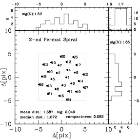
An optimal dither pattern needs to be compact, scalable, and prevent redundant pointings. Such a pattern is realized in nature in the arrangement of flower leaves (phyllotaxis) and is described by Fermat’s spiral. The above right image shows a scaled arrangement of pointings for our 27 sub-integrations. This pattern (F2D27) is the most compact and homogeneous coverage of a 2-D surface without x-y redundancy. The 10 pixel size of the F2D27 pattern in the above image has an on-sky diameter of 3.125’ or 187.5”.
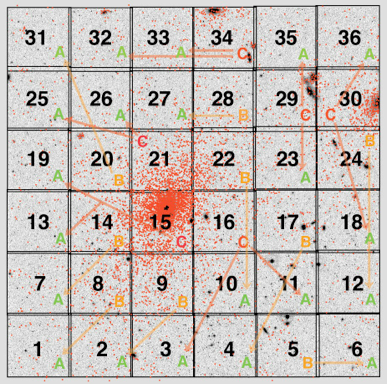
The left image shows a pixel-coverage map of our F2D27 dither pattern which is being used for each individual tile. A coverage analysis of the critical, central inter-chip gap region shows that all pixels are covered more than 16 out of 27 times, while the vast majority is covered at least 20 times. This translates into a SNR fluctuation of only 14%.
Putting it all together
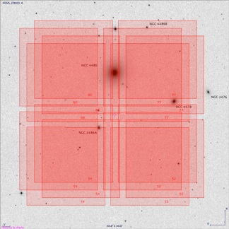
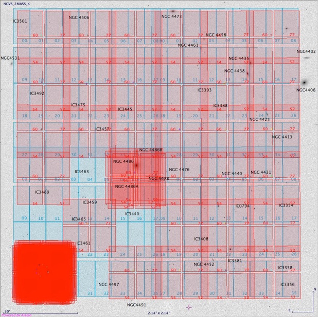
The “visit dither” (F2D27) and the “sequence dither” (4x25s) work together to homogeneously fill the entire survey area. This is illustrated in the image below where the “sequence dither” is shown for tile #15 (center of the field), while the “visit dither” is depicted for tile #1 (lower left corner of the mosaic). Each tile is offset by 19’ from its neighbor in x and y direction to assure enough overlap between tiles. The image also illustrates the overlap between the optical CFHT/MegaCam (NGVS: blue) and the near-infrared CFHT/WIRCam survey footprints (NGVS-IR: red). Four tiles with the number 2, 7, 9, and 14 have been deliberately left out for illustration purposes.